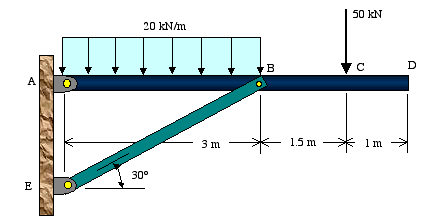
For the braced beam and loading shown, determine the reactions at the support and the force at joint B.
 |
Solution:
We begin our analysis by first drawing the free-body diagram of the beam. Once we have the unknown forces identified, we solve for them using the equilibrium equations.
Free-Body Diagram of Beam: The beam is supported by a pin at point A and a link at B. We recognize the fact that link BE is a two-force member, thus the axial force in this member is along its axis or line BE.

To simplify the calculations, RB can be broken into its rectangular components as shown below.

Reaction loads: As shown in the free-body diagram, there are three unknown reactions that need to be solved for using the equilibrium equations. Since this represents a two-dimensional force system, we can only make use of three equilibrium equations.
We begin the solution by using the equilibrium of moments with point A as the moment center. We choose point A as it contains two out of three unknown reactions.
| => |
| => |
Positive sign on the reaction indicates its assumed direction is correct. Notice that the horizontal component of RB did not appear in the above equilibrium equation as its line of action passes through point A resulting in a moment arm of zero.
Now we proceed with solving the remaining two reaction forces. Using the equilibrium of forces in the x direction gives
| => |
| => |
Negative sign means the direction is opposite to that shown in the free-body diagram. Hence, RAx is pointing to the left instead of right.
| => |
| => |
No comments:
Post a Comment