Target mean strength
MPa, water/cement ratio = 0.5, water content = 200 kg/m³. Find cement content.
Solution:
Answer: 400 kg/m³
Target mean strength
MPa, water/cement ratio = 0.5, water content = 200 kg/m³. Find cement content.
Solution:
Answer: 400 kg/m³
A simply supported beam, 6 m, carries central point load 12 kN. Find reactions and max bending moment.
Solution:
Reactions:
Max bending moment:
Answer: RA = RB = 6 kN, Mmax = 18 kNm
A simply supported beam, 8 m long, carries a uniformly distributed load of 10 kN/m over the entire span. Find:
Reactions at supports
Maximum bending moment
Solution:
Reaction at supports:
Max bending moment (midspan):
Answer:
Reactions: 40 kN each
Max bending moment: 80 kNm
A simply supported beam of length 8 m carries a central point load of 20 kN. Find:
Reactions at supports
Maximum bending moment
Solution:
Step 1: Determine reactions
For a central point load on a simply supported beam of length :
Step 2: Maximum bending moment
Maximum moment occurs at midspan (under the load):
✅ Answer:
Reactions: RA = RB = 10 kN
Max bending moment: 40 kNm
Draw the Shear and Moment diagrams for the beam. Indicate values at the supports and at the points where a change in load occurs.
Solution:


Draw the Shear and Moment Diagram for the beam. Indicate values at the supports and at points where change in load occurs.
Solution:
Let RA and RB are the vertical support reactions at A and B, and MA and MB be the bending moments at the same.
As per the Conditions of Static Equilibrium of the Structural Element:
∑Fy = 0, ∑Fx = 0, and ∑M = 0
Values at Supports:
The Shear Force at the left support A, VA = 0.5*[(-4.0)] * 1.5
or VA = -3.0 kN
The bending moment at the left support A, MA =0.5 * (-4.0) * (1.5) * ( 1.5/3)
Hence, MA = -1.5 kNm
The Shear Force at the right support B, VB = 0.5*[(4.0)] * 1.5
or VB = 3.0 kN
The bending moment at the right support B, MB = 0.5 * (-4.0) * (1.5) * (1.5/3)
Hence, MB = -1.5 kNm
Using the static equilibrium conditions,
∑Fy = 0, RA + RB = 0.5 * [4.0] * (1.5) + 4 * (2.0) + 0.5 * [4.0] * (1.5)
Hence RA + RB = 14.0 kN — eq(1)
Also, ∑M =0, hence the algebraic sum of the moments at left support is equated to zero.
Hence, RB*(5.0-1.5-1.5) = [(-1.5) – (-1.5) + (3.0)(5.0 – 1.5 – 1.5) -4.0 * (2.0) * 1.0
Hence, RB = 7.0 kN
From eq(1), RA = 7.0 kN
Shear and Moment equations:
In between A and B,
for 1.5m <= x <= 3.5m:
Shear, Vx = 10.0 – 4.0*x
Moment, Mx = VA(x-1.5) + -4.0(x -1.5)^2/2 = -2.0x2 + 10.0x – 12.0
In between B and the right end,
for 3.5m <= x <= 5.0m:
Load intensity at x, wx = 2.667x – 13.33
Shear, Vx = 1.333x*2 – 13.33x + 33.33
Moment, Mx = 0.445x3 – 6.667x2 + 33.33x – 55.55
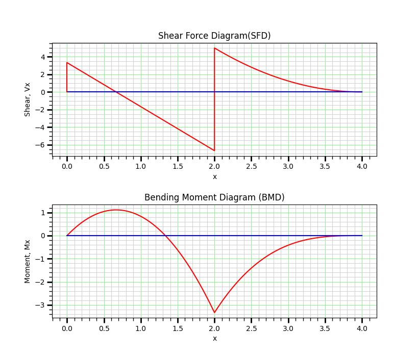
Shear Force and Bending Moment Diagram:

distance x. Shear V Moment M
0.0. 0.0. 0.0
1.5 4.0 -1.5
3.5 3.0. -1.5
5.0 0.0 0.0
Maximum +ve Shear Force, Vmax = 4.0 kN
at x = 1.5 m from the left end.
Maximum -ve Shear Force, Vmin = -4.0 kN
at x = 3.5 m from the left end.
Maximum +ve Bending Moment, Mmax = 0.5 kN-m
at x = 2.5 m from the left end.
Maximum -ve Bending Moment, Mmin = -1.5 kN-m
at x = 3.5 m from the left end.
Determine the internal normal force, shear force and bending moment acting at point C in the beam shown in the figure.
Reference: Structural Analysis by R C Hibbeler.
VB = 0.5*5*2 = 5 kN
please note that at supports, MA = 0.0 kNm, and MB = -0.5*5*2*2/3 = -3.334 kN m
Using the static equilibrium conditions, algebraic sum of moments at the left end is equated to zero.
Hence, RB = [(MB – MA – VB*(L -2) -5.0 * (2.0) * 1.0 ] / (L-2.0)
Hence, RB = 11.667 kN
Also, RA + RB = 5*2 + VB = 15 kN.
Solving gives, RA = 3.334 kN,
End support reactions are: Vertical Reactions, RA = 3.334 kN, and RB = 11.664 kN
In between A and B,
for 0.0m <= x <= 2.0m:
Shear, Vx = 3.334 – 5.0*x
Moment, Mx = VA(x-0.0) + -5.0(x -0.0)^2/2 = -2.5x^2 + 3.334*x
In between B and the right end,
for 2.0m <= x <= 4.0m:
Shear, Vx = 1.25x2 – 10.0x + 20.0
Moment, Mx = 0.41667x^3 – 5.0*x^2 + 20.0*x – 26.667
Maximum +ve Bending Moment, Mmax = 1.111 kN-m
at x = 0.667 m from the left end.
Maximum -ve Bending Moment, Mmin = -3.333 kN-m
at x = 2.0 m from the left end.
At C, x = 1 m,
Axial Force, NC = 0,
Shear Force, VC = 3.334 – 5.0*1 = -1.6667 kN
Bending Moment, MC = -2.5* 12 + 3.334*1 = 0.8334 kN-m
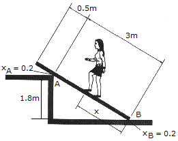
A uniform beam has a mass of 18 kg and rests on two surfaces at points A and B. Determine the maximum distance x to which the girl can slowly walk up the beam before it begins to slip. The girl has a mass of 50 kg and walks up the beam with a constant velocity.
|
The solution is;
The five-story office steel building shown in Figure 2.7 is laterally braced with steel special moment resisting frames, and it measures 75 ft by 100 ft in the plan. The building is located in New York City. Using the ASCE 7-16 equivalent lateral force procedure, determine the lateral force that will be applied to the fourth floor of the structure. The roof dead load is 32 psf, the floor dead load (including the partition load) is 80 psf, and the flat roof snow load is 40 psf. Ignore the weight of cladding. The design spectral acceleration parameters are SDS = 0.28, and SD1 = 0.11.

Fig. 2.7. Five – story office building.
Solution
SDS = 0.28 and SD1 = 0.11 (given).
R = 8 for special moment resisting steel frame (see Table 2.13).
An office building is in occupancy risk category II, so Ie = 1.0 (see Table 2.9).
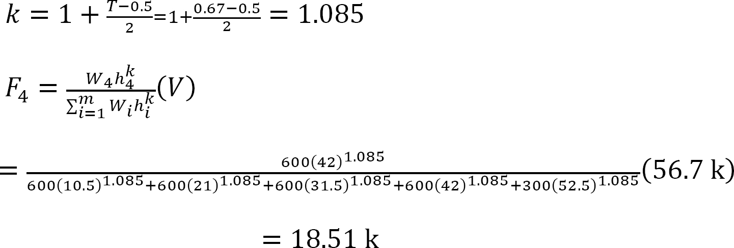
Calculate the approximate fundamental natural period of the building Ta.
Ct = 0.028 and x = 0.8 (from Table 2.12 for steel moment resisting frames).
ℎn = Roof height = 52.5 ft

Determine the dead load at each level. Since the flat roof snow load given for the office building is greater than 30 psf, 20% of the snow load must be included in the seismic dead load computations.
The weight assigned to the roof level is as follows:
Wroof = (32 psf)(75 ft)(100 ft) + (20%)(40psf)(75 ft)(100 ft) = 300,000 lb
The weight assigned to all other levels is as follows:
Wi = (80 psf)(75ft)(100 ft) = 600,000 lb
The total dead load is as follows:
WTotal = 300,000 lb + (4)(600,000 lb) = 2700 k
Calculate the seismic response coefficient Cs.
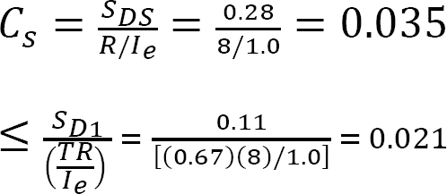
Therefore, Cs = 0.021 > 0.01
Determine the seismic base shear V.
V = CsW = (0.021)(2700 kips) = 56.7k
Calculate the lateral force applied to the fourth floor.
2.1.4.5 Hydrostatic and Earth Pressures
The reaction at support A of the beam shown in below figure, is
Solution
Simply moment at pin and roller support is zero, but if you want to how to get its value.
The principles of a differential chain block are indicated schematically in the figure. Determine the magnitude of force P needed to support the 800-N force. Also compute the distance x where the cable must be attached to bar AB so the bar remains horizontal. All pulleys have a radius of 60 mm
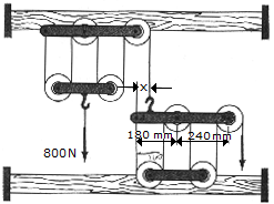
Solution
At Left block.
Each rope on left block 800/4=200N.Determine the force in each member of the truss and indicate whether the members are in tension or compression.
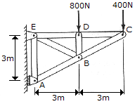
Solution
First consider a free body diagram for the whole truss structure to find the reactions at supports E and A by applying the equations of equilibrium for its external forces.
So taking summation of moment about E = 0, 3Ra-3(800)-6(400) = 0.
Ra = 1600 N.
Sum of horizontal forces = Re(x)-800-400 = 0; Re(x) = 1200 N.
Sum of vertical forces = Re(y)-Ra = 0; Re(y) = 1600 N.
Considering each member force to be a tension, each joint will be analyzed so taking joint C,
Sum of horizontal forces = 400+F(CB) sin(26.57) = 0, F(CB) = -894 N T or F(CB) = 894 N C.
Sum of vertical forces = -F(CB) cos (26.57)-F(CD) = 0; F(CD) = 800 N T.
At joint D, F(DC) = F(DE) = 800 N T F(DB) = -800 N T = 800 N C.
At joint E, Sum of vertical forces = F ED)+F(EB) sin(63.43)-Re(y) = 0.
F(EB) = (Re(Y)-F(ED))/sin(63.43) = 894 N T.
Sum of horizontal forces = F(EA) = F(EB) cos(63.43) = Re(x).
F(EA) = 1200-894 cos(63.43) = 800 N T.
At joint B, Sum of horizontal forces = 0.
F(BA) cos(63.43)-F(BC) cos(63.43)-F(BE) cos(63.43)-F(BD) = 0.
F (BA) = -1789 N T = 1789 N C.
Determine the force in each member of the Fink truss shown in Fig.
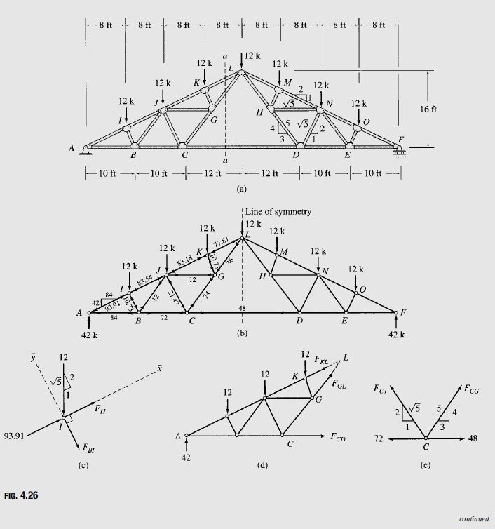
Solution
The Fink truss shown in Fig. is a compound truss formed by connecting two simple trusses, ACL and DFL, by a common joint L and a member CD.
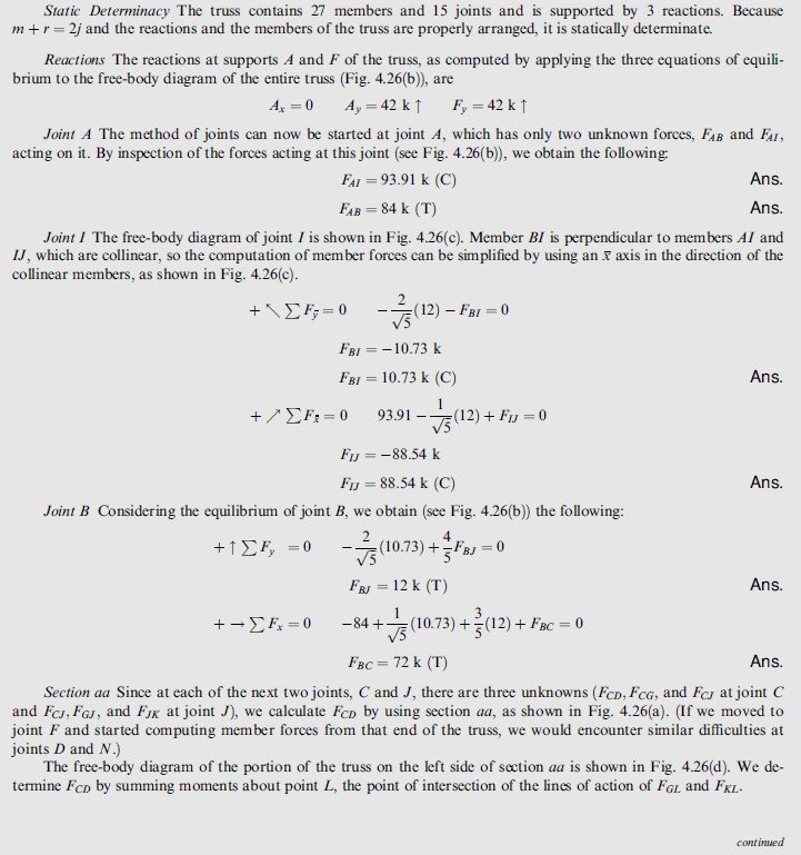
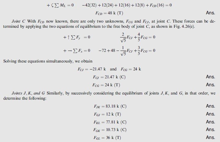
Symmetry Since the geometry of the truss and the applied loading are symmetrical about the center line of the truss (shown in Fig. )), its member forces will also be symmetrical with respect to the line of symmetry. It is, therefore, su‰cient to determine member forces in only one-half of the truss. The member forces determined here for the left half of the truss are shown in Fi). The forces in the right half can be obtained from the consideration of symmetry; for example, the force in member MN is equal to that in member JK, and so forth. The reader is urged to verify this by computing a few member forces in the right half of the truss.


